
Spring Tester for RC
Car Suspension Systems
Our client, from Monaco, is an enthusiast and business owner specializing in mini racing and off-roading RC cars. His company designs high-performance components for RC vehicles, including shock absorbers that require precise tuning. To ensure consistent performance, he needed a custom device capable of accurately measuring the stiffness of small suspension springs. Francisco approached our team at ArduinoExpert.com to develop a reliable, user-friendly Spring Tester that could measure and display spring stiffness values for different compression levels.
01. Devoforge Expertise
For this project, our team at ArduinoExpert.com applied multidisciplinary expertise in:
- Embedded systems development (Arduino-based control systems)
- Precision motion control using stepper motors
- Load cell integration and force measurement calibration
- Industrial product prototyping
- 3D mechanical design and structural optimization
- Iterative R&D and performance validation
- Human-machine interface design using Nextion display
The project required both mechanical rigidity optimization and firmware precision control to ensure repeatable stiffness measurements.
02. Client Requirements
Our client, Francisco from Monaco, operates in the mini racing and off-roading RC car industry. His company manufactures high-performance suspension systems for RC vehicles.
He required a custom spring tester to:
- Measure stiffness of small RC suspension springs
- Display stiffness in N/m
- Allow users to determine whether springs should be replaced or reused
- Provide configurable compression settings
- Be fully operational and market-ready under his own brand
He provided:
- A short video reference of a similar spring tester
- Functional specifications and expected workflow
Due to workload constraints, he outsourced full R&D and development to our team.
03. Proposed Solution
We proposed developing a fully automated spring stiffness testing system that would:
- Detect the presence of a spring automatically
- Allow the user to select compression parameters
- Apply controlled step-based compression
- Measure force at each increment
- Calculate and display stiffness in tabular format
- Automatically return to home position after testing
The device would combine precision mechanical control with real-time force measurement and a user-friendly touchscreen interface.
04. Implemented Solution
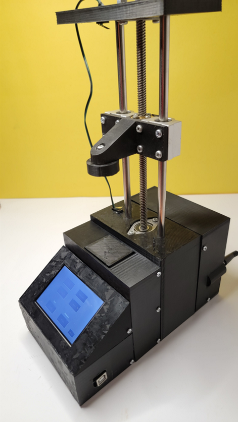
The final system included:
Core Components
- Microcontroller: Arduino UNO
- Display: Nextion touchscreen (UART via SoftwareSerial)
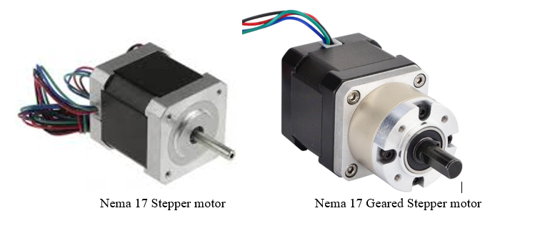
- Motor: Nema 17 Geared Stepper Motor
- Driver: TB6600 stepper driver
- Sensor: Load cell for force measurement
- Limit Switches: 2 (vertical movement control)
- Power Supply: 12V adapter
Operating Workflow
- User places the spring on the load cell platform.
- Pressing arm moves downward.
- Once spring is detected, system pauses.
- User selects:
- Step height: 1mm or 2mm
- Total compression distance: 5mm, 8mm, or 10mm
- User presses Measure.
- The pressing arm compresses the spring incrementally.
- Force values are recorded at each step.
- Stiffness is calculated and displayed in a table.
- Units can be switched.
- Pressing arm returns automatically.
- Home button allows manual reset to top position.
The final device delivered high repeatability and reliable stiffness measurement.
05. Our Process
At Devoforge, we follow a structured product development lifecycle:
- Analyzed reference video
- Defined mechanical constraints
- Selected motor, load cell, and control architecture
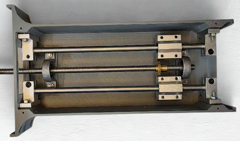
- 3D printed enclosure in two separate parts
- Integrated Arduino, motor, load cell
- Performed calibration and testing
During testing, structural flex caused inaccurate readings.
We redesigned the enclosure as a single-piece ABS structure to eliminate flex and improve repeatability.
Initial standard stepper motor lacked torque and skipped steps.
Upgraded to Nema 17 geared stepper motor, ensuring reliable compression of high-stiffness springs.
Enclosure optimized three times to:
- Improve rigidity
- Simplify assembly
- Improve aesthetics
- Increase mechanical reliability
06. 3D Enclosure Design
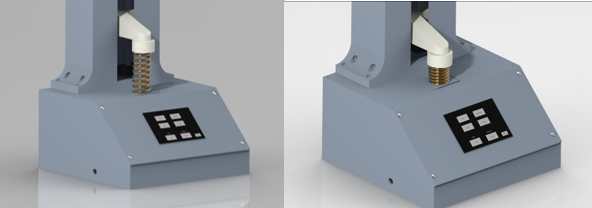
- Version 1: Two-part enclosure prototype
- Version 2: Single-body ABS rigid design
- Optimized pressing arm structure
- Integrated load cell platform
- Compact internal motor mounting
The final design improved structural stiffness and simplified assembly.
07. Circuit Design
The electronic architecture included:
- Arduino UNO as main controller
- TB6600 driver controlling geared stepper
- Load cell amplifier connected to Arduino
- UART communication with Nextion display
- Two limit switches for travel control
- 12V power distribution system
Custom firmware was developed in Arduino IDE to:
- Control stepper increments
- Capture load cell readings
- Compute stiffness
- Manage display UI
- Handle homing logic
08. Challenges
Challenge 1 – Motor Torque Limitation
Standard stepper motor skipped steps under high spring resistance.
Challenge 2 – Structural Flexibility
Two-part enclosure caused mechanical flex and inconsistent stiffness readings.
Challenge 3 – Spring Height Detection Accuracy
Originally, spring contact detection relied on load cell detection and a 0.4mm offset movement.
Due to low resolution of geared stepper motor, this method failed to provide consistent starting height.
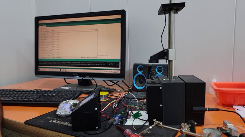
09. Revisions
Revision 1 – Motor Upgrade
Replaced standard Nema 17 with geared Nema 17 for higher torque.
Revision 2 – Structural Redesign
Converted enclosure to single-piece ABS design for rigidity.
Revision 3 – Spring Detection Mechanism Improvement
To solve height detection issue:
- Added metallic plate on load cell platform
- Made pressing arm tip metallic
- Used electrical contact detection when metal surfaces touched
This allowed:
- Precise starting position detection
- Improved repeatability
- Elimination of step-offset dependency
10. Final Version (Result)
The final version:
- Accurately measures spring stiffness in N/m
- Provides high repeatability
- Fully automated workflow
- Touchscreen-based configuration
- Reliable torque-driven compression
- Structurally rigid ABS body
The project took three months including:
- R&D
- Prototyping
- Optimization
- Testing
- Final delivery
Deliverables included:
- Working prototype
- Firmware source code
- STL files
- Circuit diagram
- Component list
- Testing documentation
After digital delivery, the client requested optimized physical prototype shipment, which was sent via UPS to Monaco.
The client expressed high satisfaction with performance, usability, and build quality.
11. Future Upgrades
The platform was intentionally designed for scalability.
Planned and potential enhancements include:
The system can be enhanced with:
- Higher-capacity load cells for larger springs
- Stronger motors for industrial-grade testing
- USB or Wi-Fi data logging
- PC-based analytics software
- Automated batch testing mode
- Integrated SD card data storage
Interested in Similar Project?
If you are developing a custom testing machine, automation device, or precision measurement system for commercial use, we can help you move from concept to fully functional prototype.
Our expertise includes:
- Embedded system development
- Motion control systems
- Load cell integration
- Custom product R&D
- 3D mechanical design
- Prototype-to-product transition