
Digital Measuring Wheel Design
for Wood Cutting Machines
For a woodworking equipment provider in Denmark, we developed an advanced digital measurement wheel solution designed to accurately track the linear distance traveled by a cutting machine during operation. The objective was to deliver a tool that enhances precision, repeatability, and operational efficiency for professional woodworkers and machine operators.
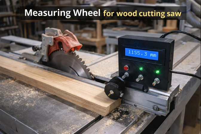
This system replaces traditional manual measurement approaches with a smart, electronics-driven mechanism that reports real-time distances in millimeters, integrating seamlessly with existing tabletop saws and guides.
01. Devoforge Expertise
At DevoForge, we specialize in embedded product development, precision measurement systems, industrial electronics integration, and rapid prototyping.
This project demonstrates our expertise in:
- Embedded microcontroller system design
- High-resolution encoder integration
- Real-time motion tracking algorithms
- Industrial-grade enclosure development
- Firmware engineering for precision calculation
- Mechanical-electrical integration in high-vibration environments
Our ability to combine mechanical design, firmware logic, and user-centric interface development allowed us to deliver a production-ready solution tailored specifically for professional woodworking applications.
02. Client Requirements
A woodworking equipment provider in Denmark approached us with the need to modernize their cutting measurement process. Traditional measurement methods such as tape measures and manual markings presented several limitations:
- Time-consuming during repetitive cut operations
- Inconsistent measurement accuracy
- No compensation for blade thickness (kerf)
- No adjustment for blade tilt angle
- Prone to operator error
- Not suitable for high-production environments
The client required an automated digital system capable of:
- Reporting precise cut length in real time
- Compensating for blade kerf and angled cuts
- Delivering millimeter-level accuracy
- Operating reliably in high-vibration woodworking conditions
- Integrating seamlessly with existing tabletop saws and guides
03. Proposed Solution
We proposed a digital measurement wheel system built around a high-resolution rotary encoder and an embedded microcontroller platform.
The system would:
- Convert rotational movement into accurate linear distance
- Apply correction factors for blade thickness and tilt
- Provide real-time visual feedback via LCD
- Offer intuitive user controls for parameter adjustment
- Be housed in a durable 3D-printed enclosure
The core measurement principle was defined as:
Distance (mm) = Pulse Count × (Wheel Circumference / Pulses per Revolution)
This ensured precise translation from rotational motion to linear measurement.
04. Implemented Solution
We engineered and delivered a complete embedded measurement system featuring:
Rotary Position Tracking
A 600 pulses-per-revolution (PPR) rotary encoder captures wheel motion with high granularity and precision.
Embedded Microcontroller
An Arduino-based control system processes encoder pulses and executes distance calculations in real time.
Blade Parameter Adjustment
The firmware allows compensation for:
- Blade kerf width
- Blade tilt angle
This ensures the displayed value represents the true cut length rather than raw feed distance.
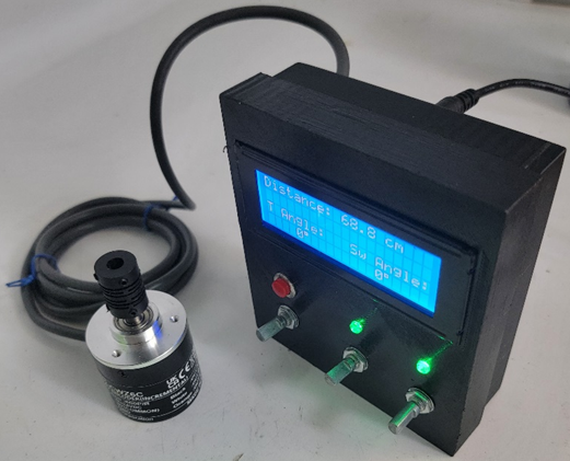
Real-Time LCD Interface
A high-contrast LCD panel displays:
- Live distance measurement
- Kerf configuration
- Angle configuration
- Calibration prompts
- Reset options
User Controls
Rotary input controls and push buttons allow operators to adjust settings without interrupting workflow.
LED Visual Indicators
RGB LED indicators provide quick system status feedback.
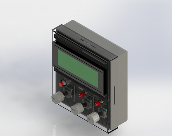
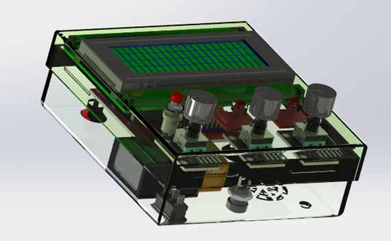
Custom 3D-Printed Enclosure
The enclosure was designed specifically for woodworking environments, offering:
- Structural protection
- Dust resistance
- Easy mounting
- Secure component housing
05. Our Process
At Devoforge, we follow a structured product development lifecycle:
We analyzed mechanical constraints, saw geometry, and operational workflows.
Initial architecture and calculation models were designed.
Encoder, microcontroller, and display modules were integrated and bench-tested.
We developed optimized firmware for:
- High-speed pulse counting
- Real-time calculation
- Error compensation
- Stable display refresh
The measuring wheel was mounted adjacent to the wood feed path, ensuring consistent contact with the material.
The system was tested under real cutting conditions to validate:
- Measurement stability
- Vibration resistance
- Accuracy under load
06. 3D Enclosure Design
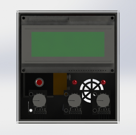
The custom housing was modeled to:
- Fit all electronics securely
- Provide ergonomic access to controls
- Include mounting points compatible with saw rails
Withstand workshop dust and mechanical shock
07. Circuit Design
The electronic system consists of:
- Microcontroller (Arduino) – System control and pulse processing
- Rotary Encoder (600 PPR) – Distance tracking
- LCD Display – User interface
- Rotary Inputs & Push Buttons – Parameter configuration
- RGB LED Indicators – Visual status feedback
The firmware processes encoder pulses and converts them into millimeter values using the defined mathematical formula while applying correction factors for kerf and tilt angle.
The circuit design ensures stable operation even in vibration-heavy woodworking environments.
08. Challenges
During development, several engineering challenges were addressed:
Vibration Noise
Wood cutting environments generate mechanical vibrations that can introduce encoder noise. Signal filtering and firmware optimization were implemented.
Mechanical Alignment
Ensuring consistent wheel-to-wood contact required precise mounting geometry.
Environmental Exposure
Dust and debris required protective enclosure design.
Accuracy Calibration
Precise calibration routines were necessary to ensure repeatable millimeter-level accuracy.
09. Revisions
Multiple iterations were performed to refine:
- Wheel pressure consistency
- Encoder stability
- User interface clarity
- Menu structure simplicity
- Housing durability
Firmware revisions improved pulse filtering and enhanced display responsiveness.
Mechanical refinements strengthened mounting stability and improved long-term reliability.
10. Final Version (Result)
The final digital measurement wheel system delivered:
- Millimeter-level measurement precision
- Real-time display of accurate cut length
- Compensation for blade kerf and tilt
- Faster workflow execution
- Reduced material waste
- Improved production confidence
The client reported:
- Significant reduction in setup time
- Increased consistency in repeated cuts
- Higher operational efficiency
- Enhanced usability for workshop operators
This solution transformed manual measurement into a smart, automated process.
11. Future Upgrades
While the current measurement wheel system delivers accurate and reliable performance for wood-cutting applications, several enhancements can further extend its capabilities and market value:
- Wireless Data Connectivity
Integrating Bluetooth or Wi-Fi would allow measurement data to be transmitted to a mobile application or desktop system. This would enable remote monitoring, digital logging, and easier analysis of cutting operations. - Cut History and Data Logging
Adding onboard memory or cloud storage support would allow operators to store previous measurements. This feature would be particularly useful for batch production, quality control, and repeat job execution. - Integration with CNC or PLC Systems
The system can be upgraded to interface directly with CNC controllers or PLCs, allowing automated feedback and synchronization with machine control logic for fully automated cutting workflows. - Touchscreen Interface Upgrade
Replacing the current display with a touchscreen HMI would improve usability, simplify configuration, and allow advanced menu navigation, especially in professional workshop environments. - Auto-Calibration Feature
Implementing an automatic calibration routine would reduce setup time and minimize human error, ensuring consistent accuracy across different machines and wheel sizes. - Higher-Resolution Encoder Support
Using encoders with higher pulse-per-revolution ratings would further improve measurement precision, making the system suitable for high-tolerance industrial woodworking applications. - Rugged Industrial Enclosure
Future versions could use an IP-rated enclosure to improve resistance against dust, vibration, and moisture, enabling long-term operation in harsh industrial environments. - Multi-Language User Interface
Supporting multiple languages would make the device more accessible for international clients and operators across different regions. - Predictive Maintenance Indicators
By monitoring wheel wear and encoder performance, the system could alert users when maintenance or replacement is required, reducing unexpected downtime. - Standalone Battery Operation
Adding a rechargeable battery option would allow the device to operate independently of machine power, increasing flexibility during installation and maintenance.
Interested in Similar Project?
At DevoForge, we design and prototype intelligent measurement systems, industrial automation devices, and custom embedded solutions tailored to real-world environments.
If you are looking to:
- Automate manual processes
- Improve industrial accuracy
- Develop a smart measurement device
- Prototype a new embedded product
We would be happy to discuss your project.